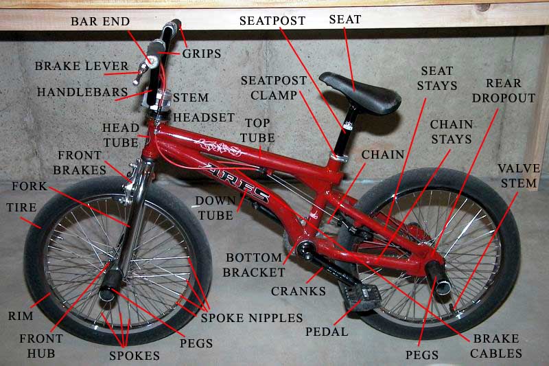
BIKE BASICS
The very first thing that every rider needs to know before working on your bike is what the heck the parts actually are on your bike and to have a good view of how a decent bike is setup. This is very important for you to know yourself, because most bike shops really don't have a clue how to setup a freestyle BMX bike. They guess, do it incorrectly, and then charge you about $75.00 per hour for their lack of skill. So while this may not be exactly like your bike... it should be relatively close.
(Click Any Image To Enlarge)
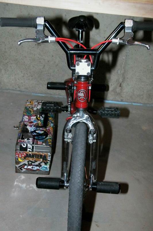 |
Front view of bike includes the handlebars, brake levers, stem, front and rear brake cables, head tube, front brakes, front wheel, forks, and pegs. |
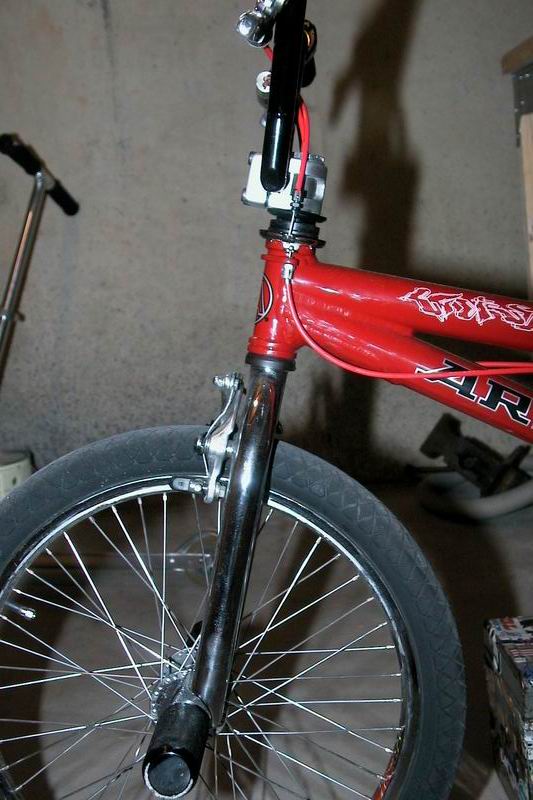 |
The side view of the front of the bike shows the handlebar alignment in comparison with the fork and the ground. Typically somewhere between straight up and down (90 degrees) and the angle of the fork. Head tube angle is measured from the ground upwards in degrees. So a steeper head tube is closer to 90 degrees which is straight up and down. Also notice that the front wheel is slightly forward in the fork and that the handlebars are mounted forward on the stem. This is called offset. There are zero offset forks and handlebars available, but this is personal preference. |
 |
View of front of bike with the handlebars backwards. Notice the front brake cable that comes in from the left side of the bike and how it goes down through the stem into the fork and head tube then comes out of the bottom of the fork and loops around to the front brakes. This is an excellent image of exactly how the front brake cable should be run to achieve maximum braking performance. |
 |
Close-up view of the handlebars and the stem offset as well as the angle the bars are mounted at. Note the brake cables coming down into the detangler. |
 |
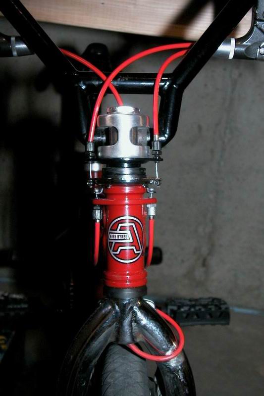
Here is a close-up view of the brake cables and stem interaction. The cable coming in from the left is the front brake cable and goes down the hollow stem bolt into and through the forks. The two cables on the right are going down into a detangler. Note the large bolt on top of the silver stem, this is called the compression bolt. |
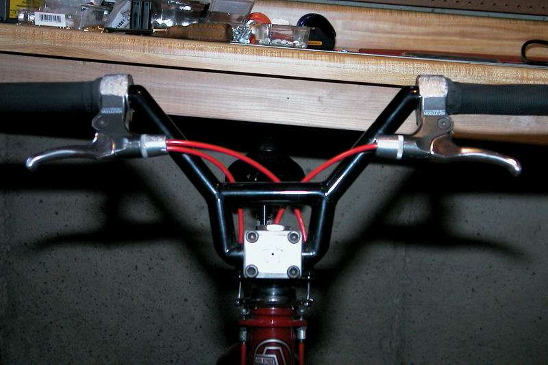 |
This view of the handlebars clearly illustrates the crossbar height as well as the routing of the brake cables around the bars. With a high crossbar riders often run the cables under the crossbar. But, with a low crossbar like this, the cables go over the bar. Brake cables are typically run very short and close to the bar if possible. |
 |
This is the top view of the right brake lever and grip. Specifically, this brake lever has a hinge on it that allows the lever to be removed from the bike without removing the grips. Also notice that after about a year or two of serious riding and a lot of falls the lever gets a ton of wear and makes the hinge almost unusable. |
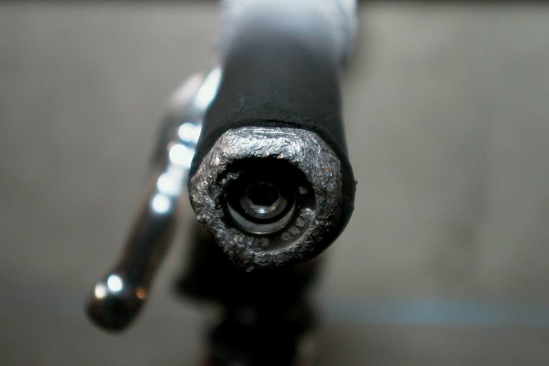 |
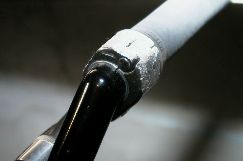
Hey, look at this, it's the bar end on the handlebars. This is an aluminum bar end that has an hex screw on it to hold it in place. Internal guts keep in from slipping out or moving at all. Also note the extensive wear on this piece from about a year of riding. |
 |
This is the left brake lever which in the United States typically is connected to the front brake cable. A single cable is coming out of the lever and clearly shown on the left side of the image is a large silver bolt that can be adjusted out to help eliminate slack in the brake cable. |
 |
This is a rear view of the left brake lever. Note that the grip is pressed up against the side of the lever and that the cable that comes into the lever is accessible from underneath the lever. This makes it possible to install new brake cables easily. |
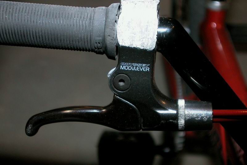 |
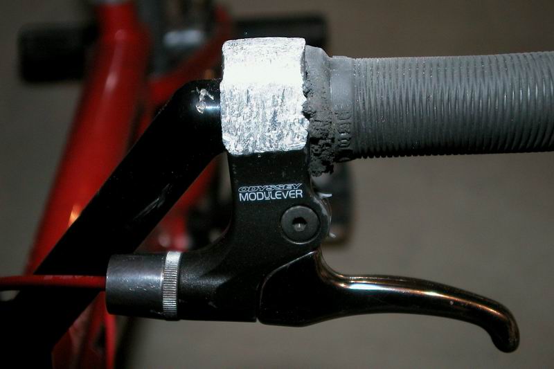
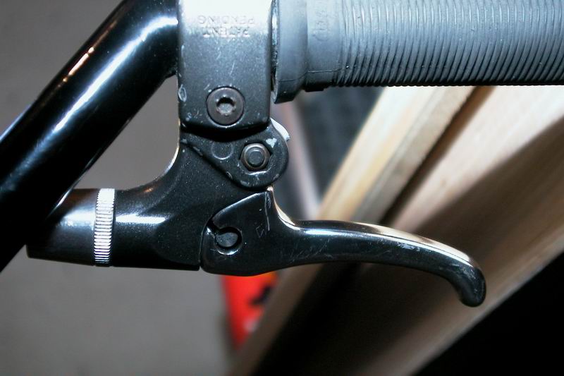
A top view of the right brake lever here and you can see that this particular lever allows for dual cables to come out of it for the rear brakes. This is called a Modulever and is made by Odyssey. The two cables go down into the detangler and provide smoother rear brake cables. |
 |
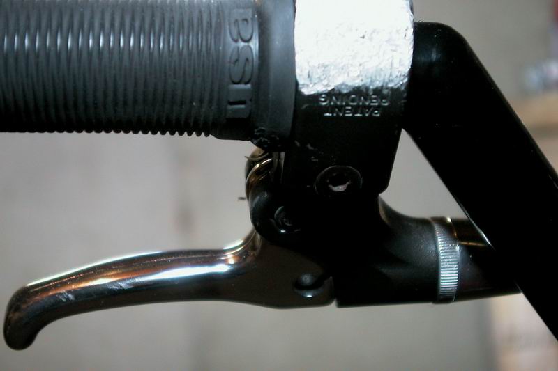
The rear view of the right brake lever is not much different than that of the left brake lever. Of special note is the small lip on the edge of the grip where it meets the brake lever. This is called the grip flange. On some grips this flange is much larger than on other grips. Personal preference really comes into play with grip flanges. |
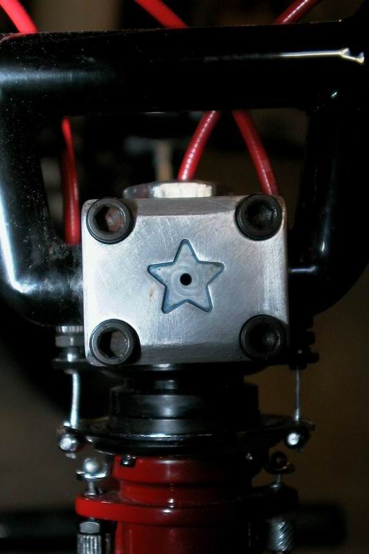 |
A close view of the stem and the crossbar of the handlebars here. You will see that there are four bolts on the front of the stem that hold everything in place. You can also see the compression bolt on top of the stem that the front brake cable goes down into. Between the four bolts on the front of the stem, and the compression bolt on top of the stem, the handlebars and fork are held firmly in place so that the bars don't move and the fork can steer smoothly. |
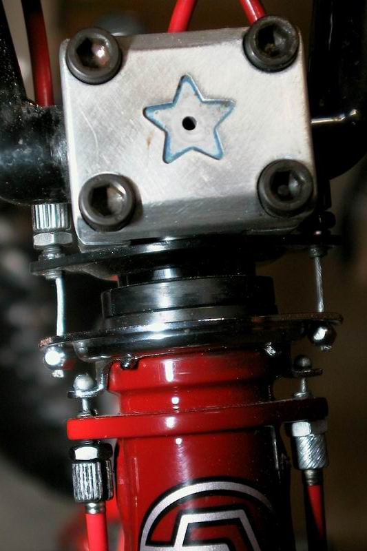 |
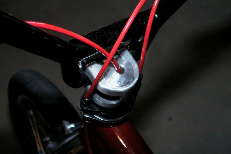
Just under the stem are two separate items. The detangler, going by the 'trade' names of a Gyro or Oryg typically, is made up of three different plates. The top plate has the upper cables going into it. The bottom plate has the lower brake cables going into it and in this case is built into the bicycle frame (red). The middle plate is the actual detangler and floats between the two plates, moving up and down as the back brakes are pulled. The black pieces between the stem and the head tube (red area) is called the headset and contains the ball bearings that allows the fork to spin. |
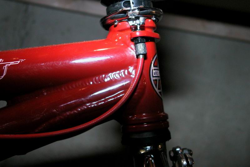 |
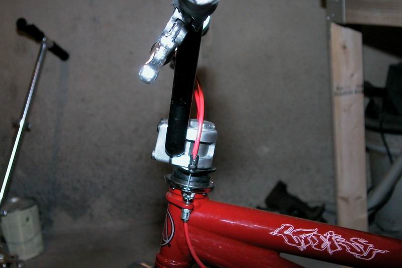
A side view of the front of the bike. Note the lower rear brake cable coming out of the lower detangler plate that is built into the bike. The head tube is the red round tube that the fork passes through on the front of the bike. Also notice that there is a extra piece of metal coming off the head tube attached to the lower tube on the frame. This is called the heat tube gusset and reinforces the frame. |
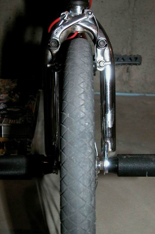 |
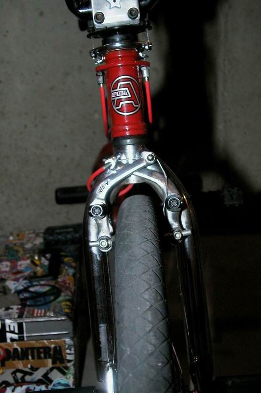
Hey! A front view of the front tire of the bike. You get a good view of the forks coming out of the head tube, the front brakes, and the pegs coming off the axles of the bike. Of note? Nothing much here, just keep in mind the fork has the left fork leg (right side of picture) and the right fork leg (left side of picture) and in this view you can clearly see that the ends of the front brake pads are posts with no threading on them. |
 |
Looking down on the front wheel you can see all the spokes on the wheel, the hub, brakes, rim, and tire. You also get a little more detail of the thread of the tire. The tread is the pattern molded into a tire that grips the ground, allows you to roll faster or slower, and provides traction to your foot if you use it to scuff the tire. |
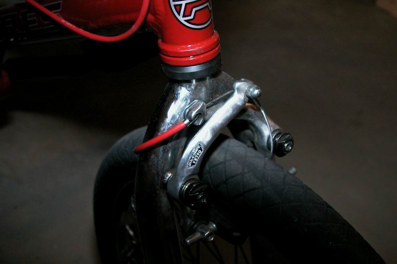 |
A close up of the front brakes which helps to detail how the front brake cable comes into the brake from the side. Notice how close the brakes are to the fork. Also, you can see a black piece at the top of the forks, under the head tube. This is the lower bearing cup for the headset and has bearings in it to allow the fork to spin. |
 |
Another view of the front brakes, head tube, and tire. |
 |
This is the front hub of the bike. Spokes are intertwined coming out of the hub to provide strength in supporting the rim of the bike. The hub has an axle running through the center of it, and ball bearings inside the wheel to allow it to spin freely. The metal pieces that the spokes come out of are called the hub flanges. |
 |
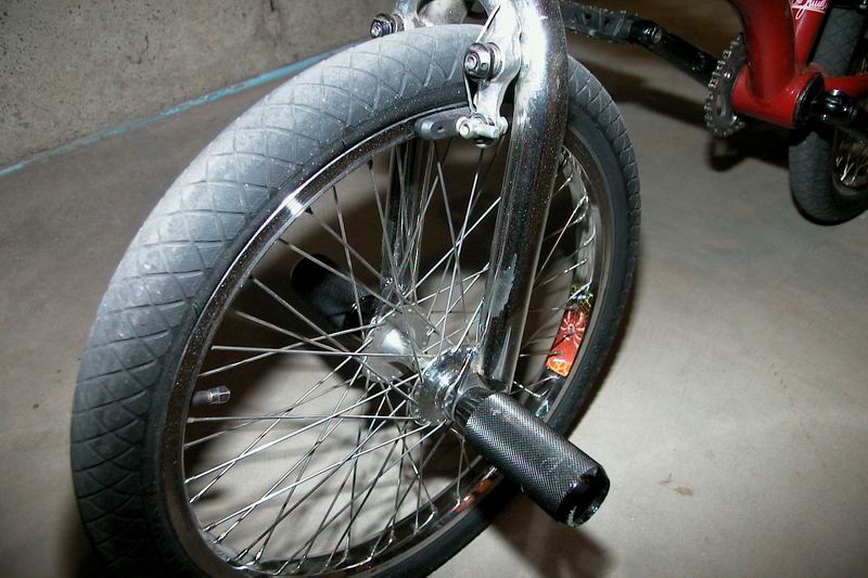
This is the front peg on the bike and has little grooves cut into it which are called knurling. Also, the pegs are tapered at the end of them and smoother at the end. This allows your foot to rotate on the tip of the peg easier. Finally, notice that the peg is hollow. The peg itself simply slides onto the front axle of the bike, then a nut is installed into the peg which holds it onto the fork of the bike. |
 |
A close up of the base of the fork. This narrow strip of metal is called a dropout. The fork dropout is pinched between the front wheel and the peg by a bolt inside the peg and two nuts between the dropout and the front hub. Hopefully you can see the two nuts in the photo clearly. The inner nut is the cone and actually presses against the bearings in the hub to hold them in place. The outer nut is pressed against the fork and locks against the inner nut to keep it from moving. This is called the locknut... kind of makes sense. |
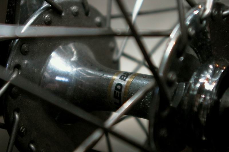 |
An extreme close-up of the hub which highlights the flanges and the center portion of the hub. This hub uses steel ball bearings which are mounted inside a steel cage and are called sealed bearings. Sealed bearings are used on inline skate wheels and skateboard wheels are are used on almost every high performance BMX bike wheel. |
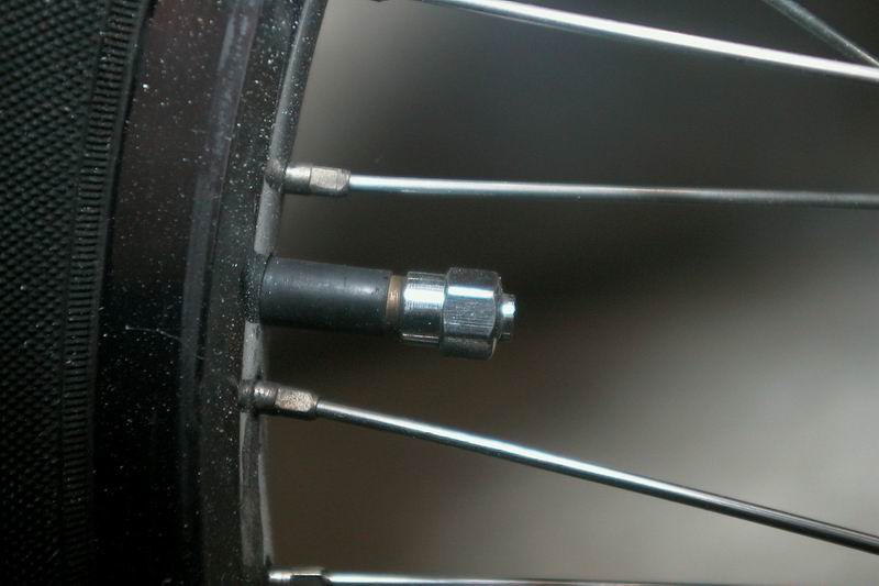 |
This view shows the black valve stem coming out of the rim of the bike with a silver valve stem cap on it. The valve stem allows you to put air in the tires of the bike. Also note the spokes going into the rim, they all have a little piece on the end of them. That piece is called the spoke nipple, and is a nut that tightens the spoke. |
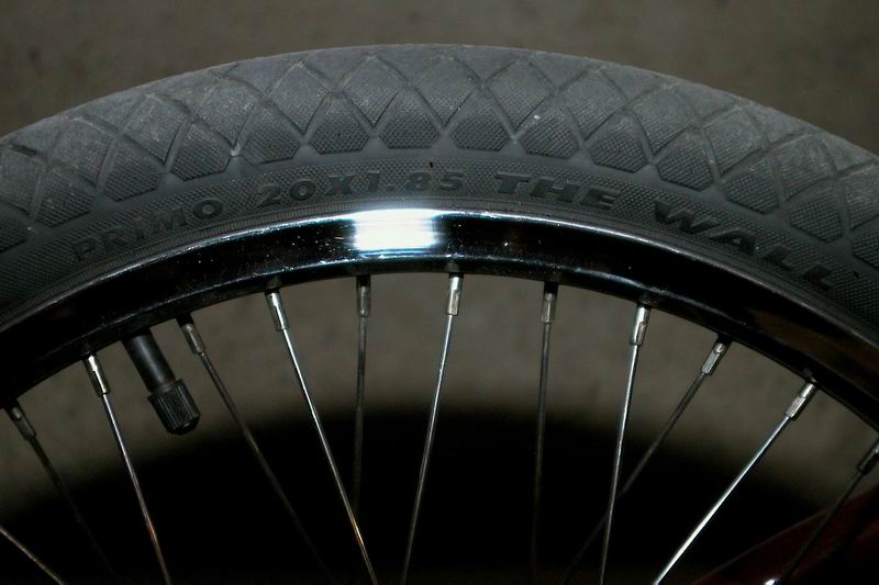 |
Tires in general have information printed on the side of them. In this photo you can see the manufacturer name, Primo, the tire name, The Wall, and the tire dimensions. 20x1.85. Well, that means that it is a tire for a 20 inch wheel which almost all BMX wheels are and it is 1.85 inches wide when inflated. |
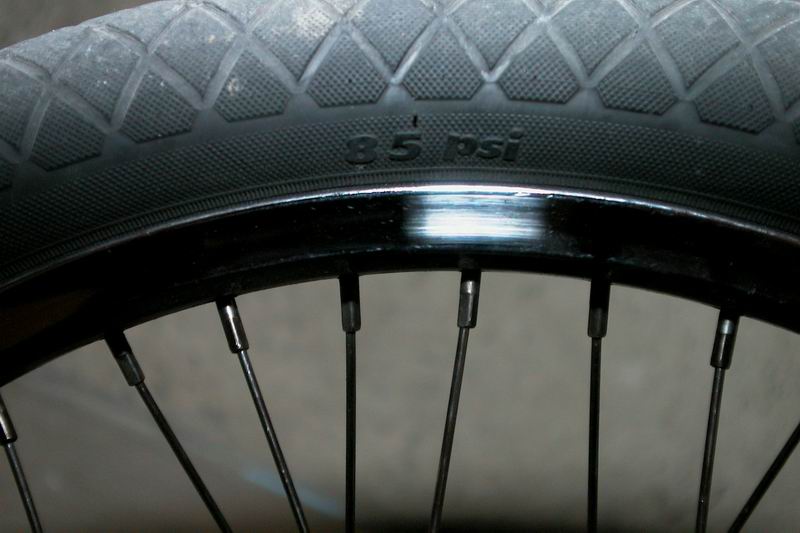 |
Another marking on the side of the tire is how much air pressure the tire can handle. This one states 85 PSI which means 85 pounds per square inch of pressure. Also note how shiny the rim is. This is a chrome plating over an aluminum rim which dramatically improves braking performance in dry weather. |
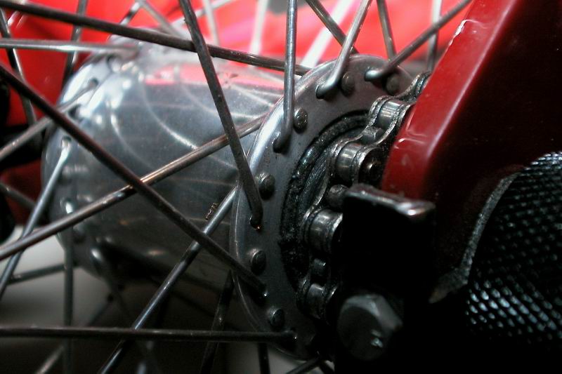 |
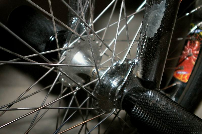
Switching from the front to the back wheel, we can see the rear hub on the bike. This hub is called a freecoaster (details in the hubs section) and has loose ball bearings in it. You can see that the flanges on this hub are much lower than those on the front hub. Also you can see the chain coming in on the right side of the hub. |
 |
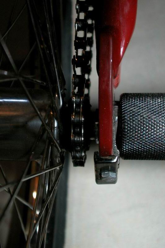
Here's a view of the chain tensioner. Its function is exactly what it says. That is, it keeps the chain of the bike tight and doesn't allow it to come loose and fall off. Chain tensioners wrap around the rear axle and pull it backwards, pulling the rear wheel back and keeping everything tight. |
 |
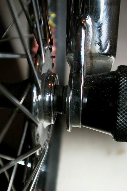
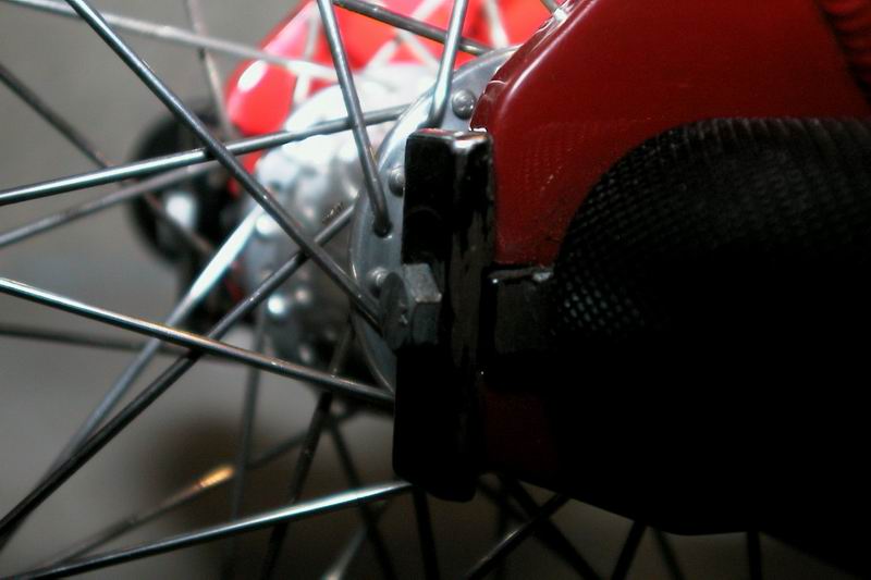
Looking down on the rear dropout (red) pinched between the peg and the rear sprocket of the bike. Similar to the fork photo above, the rear dropout is pinched between the peg and the lock nut of the rear hub. Also you can see the chain tensioner washer between the peg and the dropout. Added as well is clearance for the chain to come in and wrap around the rear sprocket. The rear sprocket is the round piece with 'teeth' on it at the back of the bike. |
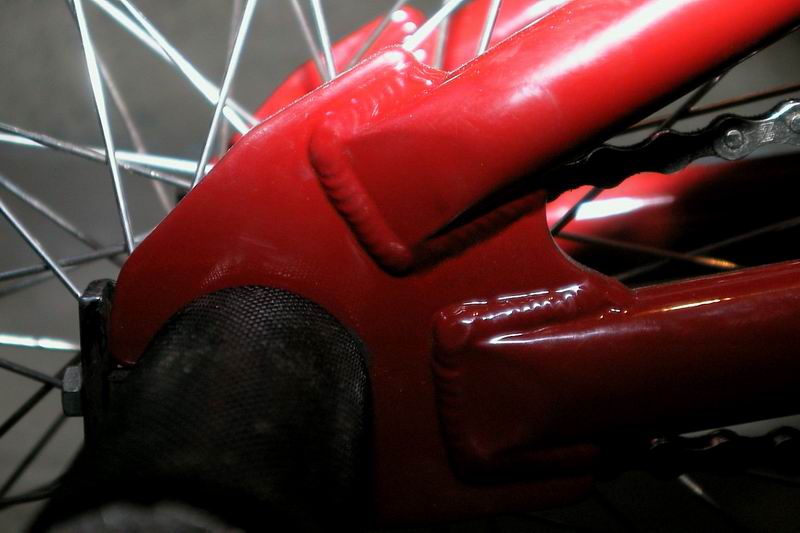 |
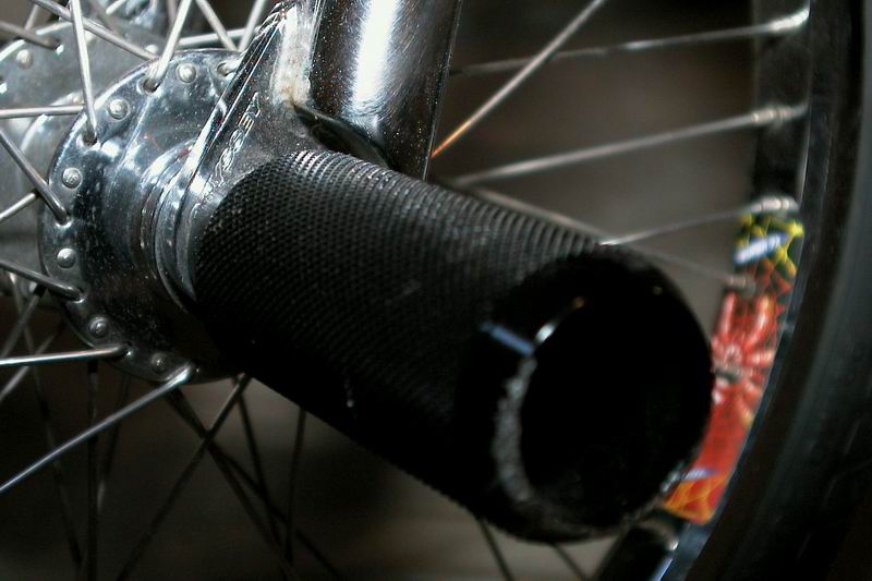
A good view of the rear dropout here. Notice how there are two tubes coming out of it and how large and flat it is. The flat surface allows for the rear peg to press flush against the sides of the dropout and provides additional strength to the frame in the rear triangle (see below). |
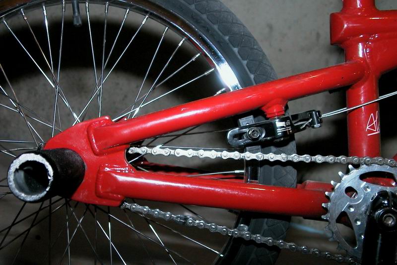 |
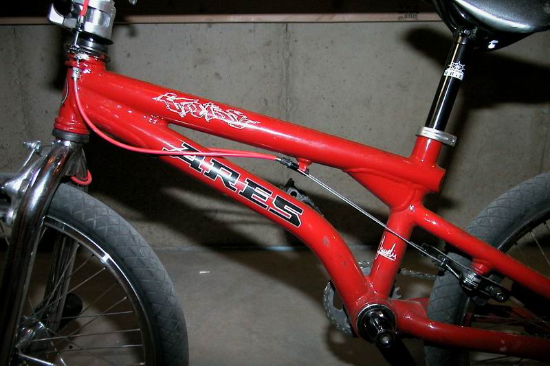
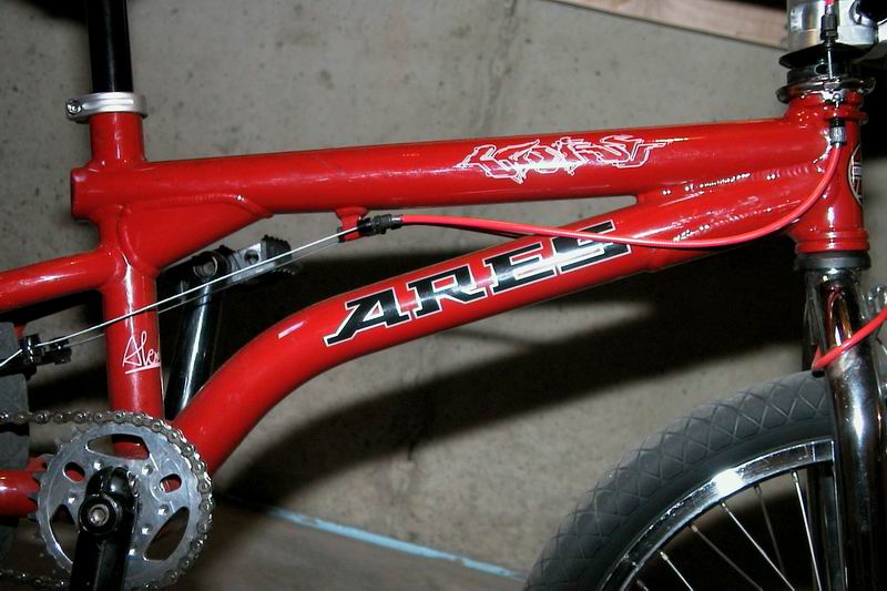
The rear triangle of the bike. A bike basically is made up of the front and the rear triangle. The rear triangle has the seatpost tube, which the seatpost goes into, the seat stay (upper tube), and the chain stay (lower tube). You can also see the front sprocket and chain here and the back brakes of the bike as well as rear wheel placement. |
 |
Another view of the rear triangle which shows a better view of the rear brakes and the seat stay. Notice how the seatpost tube is going into a connector at the bottom. This is called the bottom bracket and supports the bearings which the cranks use run on. Notice the twin cables running into the rear brakes. |
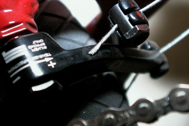 |
A close up view of the rear brakes. These are U-brakes which have two completely separate arms with brake pads attached. There are springs in the arm under the bolt where it says "- +" on the arm which provides tension on the brake arm. You can also see the brake cable going through a special nut which holds it in place. |
 |
The rear brake pads on this bike are different than the front brake pads. You can clearly see that this brake pad has a bolt on the end of it. This means that the brakes accept brake pads which have threaded posts on them. The front brakes of this bike have non-threaded posts and the brake itself holds the pads in place. |
 |
Here we are with a pretty good view of the front triangle of the bike. The top of the triangle is called the top tube and runs between the head tube and the seat tube. The lower tube runs from the head tube to the bottom bracket and is called the down tube. The sharp bend in the down tube gives additional room to get your foot in place. |
 |
Same picture, other side. Notice how the lower brake cables are run and the angle of the seat tube. This angle is measured similar to how the head tube angle is. From the ground upwards to a 90 degree angle. The lower the number the more laid back the seat tube will be and the farther from the front of the bike your seat will be positioned. |
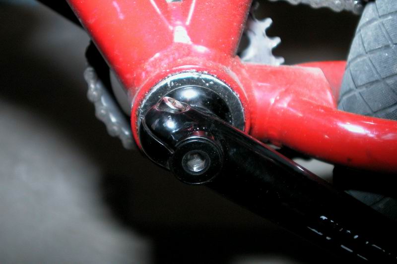 |
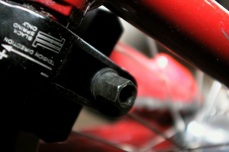
Up close with the bottom bracket and crank arm. See how the crank arm has one bolt on the end of it and one bolt on the side of it. These two bolts keep the crank arm attached to the crank spindle which runs through the center of the bottom bracket. More details of how this all works is in the 'cranks' section of the site. |
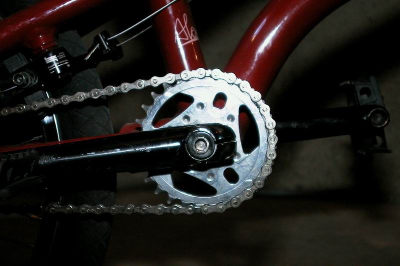 |
Flip around to the other side and you see the right crank arm and the front sprocket of the bike. There are about 26 teeth on this sprocket, which is very low compared to many other bikes. The small size gives more clearance for legs and shins to help reduce injury. It combines with a small rear sprocket to still allow pedalling to be effective, though this is often personal choice. |
 |
An underside view of the bottom bracket, crank arms, sprocket, and chain. You can see how everything goes together here. You should also note that (part of) the serial number for the frame is stamped into the bottom bracket on the bottom of the bike. Typically this location, or the rear dropout, is where you will find your serial #. |
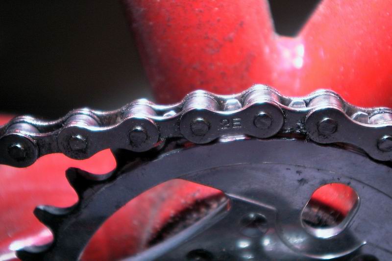 |
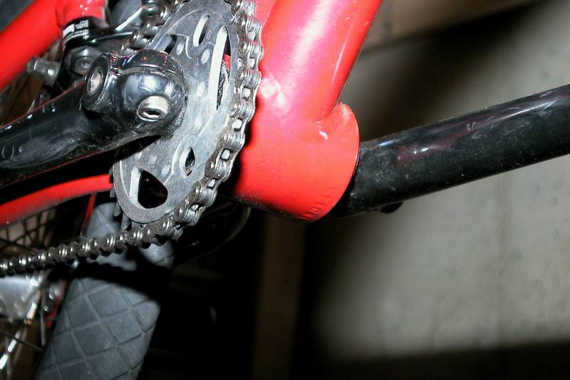
See how the chain connects with the front sprocket? The prongs that the chain meshes with are called teeth. Front sprockets typically have between 24 and about 46 teeth on them. As more teeth are added to the front sprocket, the sprocket will get larger and the chain will have to be made longer to accommodate the increased in size. |
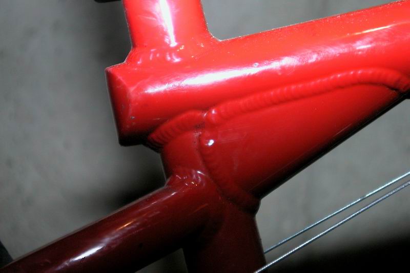 |
This is the junction point between the top tube, seat tube, and seat stays of a bike. Most notably is a large gusset that has been welded at this junction point to increase strength. Gussets, in general, may be added to any point on a bike where additional strength is needed or a manufacturer wants to add it. |
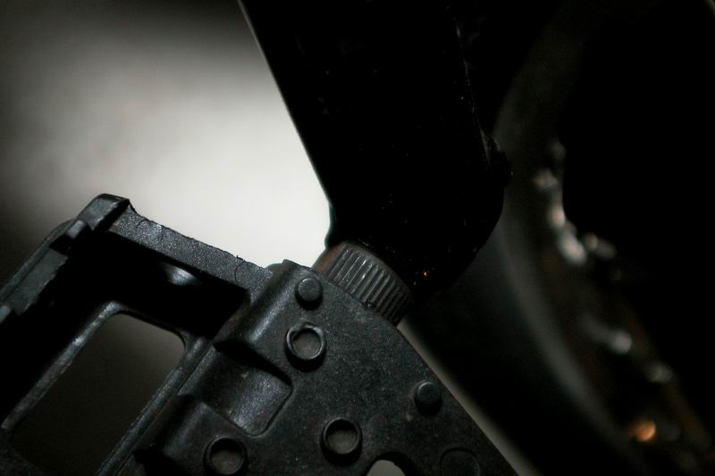 |
The pedal has a piece of metal running through it called the spindle. The spindle of your pedal is either 1/2 an inch wide if you have 1-piece cranks, or is 9/16 of an inch wide if you have 3-piece cranks. You can tell in the photo that the pedal spindle is flat on two sides to put a wrench on it. |
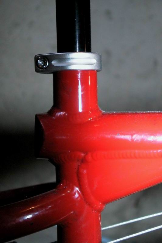 |
Another view of the junction of the top tube, seat tube, and seat stays. A little further back we see the seat post clamp and the seat post coming out of the seat tube. It should be noted that the minimum distance for the seat post to go into the seat tube is about an inch or two below the junction point where the top tube meets the seat tube. Better yet would be to make sure the seat post goes down at least as far as the seat stays on this particular bike. |
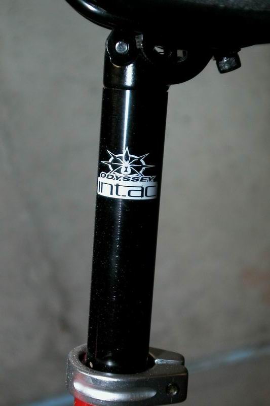 |
The seat post has a couple of main things to look for. One, is that some seat posts have integrated seat clamps, and others require a separate seat clamp. This one is integrated. Secondly, seatposts come in a huge number of sizes, and you must get the exact size seat post, and seat post clamp that is correct for your frame. If you do not know what size it is, take it to your local bike shop and have them measure it for you. They will be happy to do that for nearly free. Try to buy at least something from them for the service! |
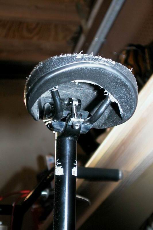 |
An underside view of the seat and the seat clamp. While every seat typically ships with a seat clamp, called 'guts' that will attach to a 7/8 inch seat post, some seat posts have integrated guts like this one does. The seat post guts wrap around the two metal rails the support the seat. Seat rails can sometimes be tricky to make fit into your seat guts, but with some coaxing can typically be popped into place. Also note that the back of the seat has had some friendly encounters with the pavement causing wear and tear. |
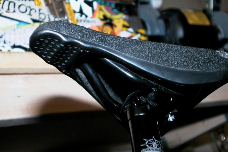 |
The front of this seat has some very obvious finger indentations which are supposed to make grabbing the seat easier. This is, more or less, a flatland specific seat called the Primo Steroid. It is entirely made out of plastic and offers no padded seating area like many seats do. Definitely pick a padded seat if you want to sit down a lot. |
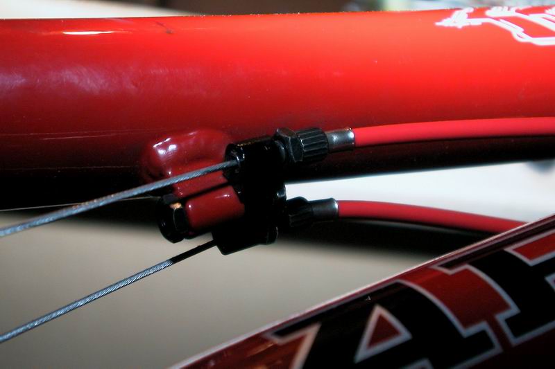 |
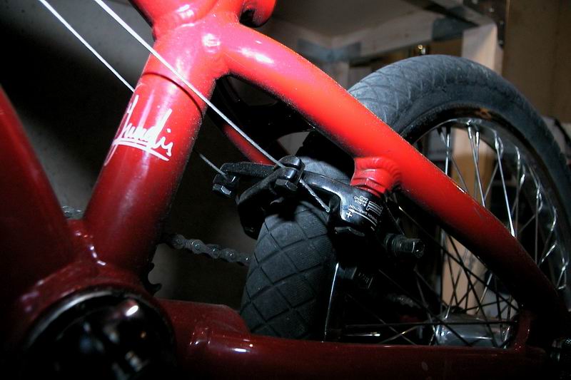
The London Mod is not a new concept but now is the name of the device that allows you to run two brake cables from a detangler to the back brakes. This setup has a London Mod (black piece) mounted on the underside of the top tube with the red brake housing going into it. The two brake cables are seen emerging on the other side. |
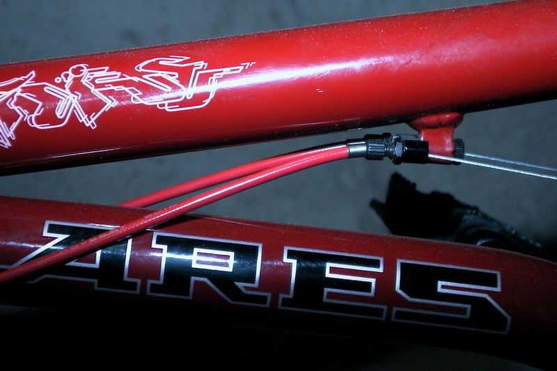 |
Another view of the same thing. This more clearly shows how the cables are running along the side of the bike and into the London Mod. The angle that the brake cables emerge from the London Mod should almost exactly line up with the angle your rear brakes are mounted at on a well designed frame. |